|
Today’s spectrum is very crowded and complex. The demand for more data is driving research to potentially utilize centimeter-wave and millimeter-wave frequency bands for 5G high data throughput applications. These frequency bands offer the potential for contiguous blocks of additional spectrum that is not available in today’s sub 6 GHz frequency band. However, there is also interest in utilizing today’s sub 6 GHz spectrum more efficiently for 5G applications. This is driving research for new 5G candidate waveforms to improve out-of-band spectrum suppression, and to utilize spectrum more efficiently.
Operating in the already crowded sub 6 GHz spectrum poses questions as to how new 5G candidate waveforms and legacy 3G and 4G waveforms will interact and coexist with each other. While some scenarios can be explored with field testing, it can be beneficial for researchers and engineers to explore many different potential coexistence scenarios in the R&D lab environment before field testing with actual hardware. Flexibility is key to being able to explore many scenarios in the R&D lab environment with different waveform types, frequencies, and parameters before field testing in which the test scenarios may be more limited.
This two-part article shows a flexible R&D coexistence testbed, which combines design simulation with test equipment to evaluate potential 5G coexistence scenarios. Three coexistence scenarios are explored. The first scenario shows a sub 6 GHz coexistence case study with a notched filter bank multicarrier (FBMC) 5G candidate waveform and a 4G LTE waveform centered in the FBMC notch. The FBMC notch width was then varied to evaluate LTE EVM as a function of decreasing notch width. The second scenario, which will be discussed in part 2 in the next issue, expands on the initial case study by introducing simulated RF impairments from a modeled transmitter design to provide insight into how RF designs might impact waveform coexistence. A more complex third scenario is then examined with multiple and different 5G candidate waveforms combined with 3G, 4G, and personal area network (PAN) waveforms.
5G Candidate Waveforms
There are many waveforms being researched for 5G applications, but several of the candidate waveforms are discussed briefly below.
The first one is orthogonal frequency-division multiplexing (or OFDM), which is currently used in 4G and, for that reason and more, it is under consideration for 5G through the use of filtered OFDM (or F-OFDM).
The second one is FBMC, or filter bank multicarrier. FBMC applies filtering on a per-subcarrier basis to provide improved out-of-band spectrum characteristics. It uses a flexible approach to baseband filtering, using either a polyphase network or an extended IFFT filter.
The third one is UFMC, or universal filtered multicarrier. UFMC applies filtering on a per-sub-band basis instead of a per-subcarrier basis as with FBMC. One potential benefit of UFMC is reduced complexity of the baseband algorithms.
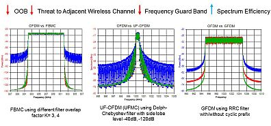
Figure 1 shows how the steeper spectrum roll off of some of the 5G candidate waveforms are related to spectrum efficiency.

Figure 1: Simulated spectrums for OFDM, FBMC, UFMC, and GFDM.
This simulation case study in figure 1 shows that the proposed new waveform technologies FBMC, UF-OFDM (UFMC) and others potentially have improved out of band performance relative to OFDM, and thus may offer the potential for smaller frequency guard band to achieve higher spectrum efficiency. However, in part 2 of this article we will also examine how RF impairments can be a consideration in this.
We’ll now evaluate a coexistence case study with an FBMC 5G candidate waveform combined with a 4G LTE waveform to evaluate how out-of-band spectrum emissions can impact coexistence and guard band requirements.
First Case Study: 5G Candidate FBMC Waveform with a 4G LTE Waveform
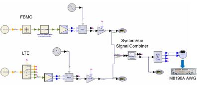
For this case study, we used a sub 6 GHz coexistence testbed that was demonstrated at the 2016 International Microwave Symposium (IMS) tradeshow. The LTE and FBMC signals are generated using the design software schematic shown in figure 2. The design software is a system-level simulator which can be used to construct system-level designs, evaluate design performance, and perform design trade-offs.

Figure 2: FBMC and LTE coexistence waveform generation.
The FBMC signal source and the LTE signal source are shown on the left side of the schematic. They generate complex waveforms, which are then modulated onto a carrier using IQ modulators. The FBMC and LTE waveforms are fed into a SignalCombiner element, which re-samples the two waveforms and combines them into a single composite waveform that is downloaded to an arbitrary waveform generator (AWG). The output of the AWG is analyzed using an RF signal analyzer and vector signal analysis (VSA) software.
One of the challenges with combining multiple types of waveforms is that they can have different center frequencies, different bandwidths, and different sample rates. This can make it challenging and difficult to combine many different and disparate waveforms.
Fortunately, recent breakthroughs in simulation arbitrary resampling technology has enabled multiple input signals with different center frequencies, bandwidths, and sample rates to be combined. This is made possible with the SystemVue Signal Combiner element, which effectively re-samples multiple input signals and combines them together to create one composite output waveform with a user-defined sample rate which can be set for the AWG. This enables signal scenario flexibility to create complex waveforms in simulation which can then be downloaded to the AWG to create coexistence test signals for the R&D lab environment.
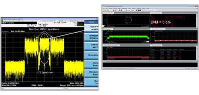
To evaluate the coexistence of the LTE signal in the presence of the FBMC signal, the test scenario is modified in simulation to notch out some of the active subcarriers in the FBMC signal. The LTE center frequency is then set so that it was centered in the notch.

Figure 3: Analyzing the EVM of an LTE signal coexisting within a notched FBMC waveform.
The upper-right display in figure 3 shows the measurement result using the VSA software on the RF signal analyzer. The LTE EVM result is approximately 0.6 percent, which indicates that the FBMC out-of-band characteristics are having a minimal impact on the LTE signal for this particular notch configuration.
Although not shown in this article, the FBMC notch width was then varied to evaluate LTE EVM as a function of decreasing notch width. This type of scenario could be useful in determining how much guard band is required for coexistence between the two waveforms to maximize spectral efficiency. EVM is used in this case study as the metric for waveform quality, and as a measure of the interference impact. Bit Error Rate (BER) or throughput could be another metric of interest for a receiver.
The second scenario, which will be discussed in a follow-up article, expands on the initial case study by introducing simulated RF impairments from a modeled transmitter design to provide insight into how RF designs might impact waveform coexistence. This involves inserting a modeled transmitter design to the right of the FBMC source (figure 2). The power amplifier (PA) 1 dB compression point is then varied to evaluate the impact to FBMC LTE coexistence in simulation. In addition, a more complex coexistence scenario is examined with multiple and different 5G candidate waveforms combined with 3G, 4G, and personal area network (PAN) waveforms.
by By Greg Jue, Applications Development Engineer/Scientist, Keysight Technologies, Inc.
| 

